Who is this switch best for?
- Office LAN expansion
- CCTV and IP camera networks
- WiFi access point connectivity
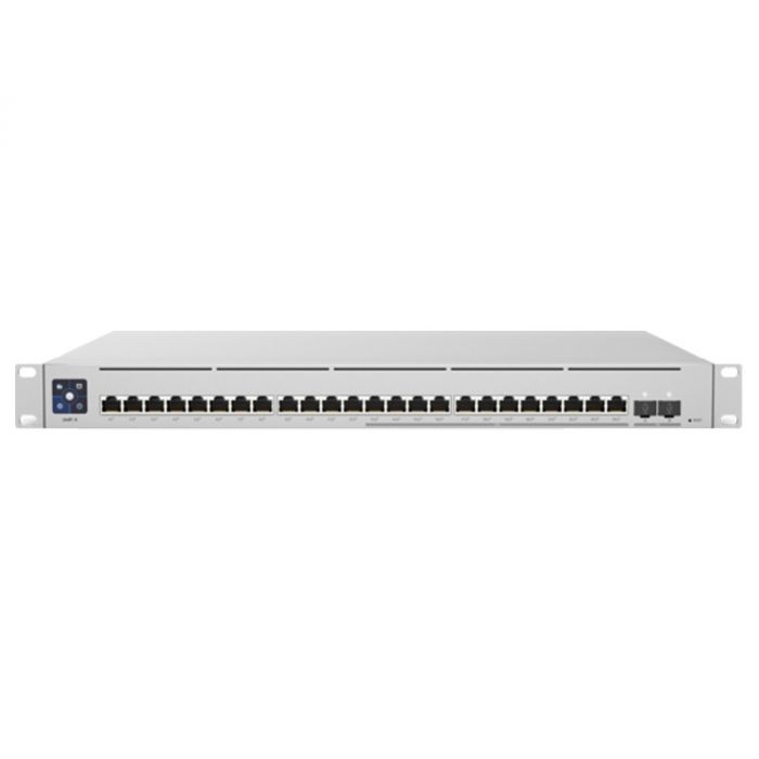
Works with standard Ethernet networking equipment including routers, computers, IP cameras, access points and servers. Confirm port, PoE and mounting requirements before purchase.
Check the product label or manufacturer datasheet for exact input voltage, power adapter and PoE requirements.
The Ubiquiti UniFi Switch 24 PoE, model USW-24-PoE, combines wired networking, power for compatible endpoints and centralized management in a rackmount switch. It suits offices, schools, retail premises and smaller hospitality installations with a mixture of computers, cameras, phones and wireless access points.
It provides 24 Gigabit Ethernet ports, with PoE+ available on 16 ports, plus two dedicated Gigabit SFP interfaces. Its 95W shared PoE budget makes careful device selection important: the number of powered connections does not mean every connected device can draw its maximum simultaneously. Tech Specs
Request the current Ubiquiti UniFi Switch 24 PoE price in Kenya from Network Switch Kenya, including suitable cabling, optical accessories and installation services.
The USW-24-PoE, also called UniFi Standard 24 PoE, is a managed Layer 2 switch administered through UniFi Network. It provides a common connection point for ordinary Ethernet equipment and compatible powered endpoints.
This is different from the USW-Pro-24-PoE. The standard model has a smaller power allowance and Gigabit SFP uplinks rather than the Pro model’s faster SFP+ arrangement.
It also differs from older UniFi switches carrying similar “24 PoE” names. Confirm the exact USW-24-PoE model on the quotation and equipment label.
Specifications follow Ubiquiti’s current technical information and hardware guide. Tech Specs
PoE simplifies installations where a mains adapter beside every endpoint would be inconvenient. Compatible cameras, phones and access points can receive power and network data over the same cable.
Check each device’s required standard and maximum consumption. Passive-PoE equipment and higher-power endpoints should not be assumed compatible.
Connections for Powered and Ordinary EquipmentThe combination of powered and non-powered ports suits installations where only some endpoints need Ethernet-delivered power.
Computers, printers and recorders can use ordinary connections, preserving powered ports for equipment that needs them.
Centralized UniFi AdministrationUniFi Network provides a shared administration environment for supported equipment.
This can simplify configuration and maintenance when the installation already uses UniFi devices. Plan where the application will run, who owns the site and how access and backups will be maintained.
Dedicated Fiber UplinksThe SFP interfaces provide optical connection options while leaving copper ports available for endpoints.
Select compatible modules and match fiber type, wavelength, connectors and distance at both ends.
These uplinks operate at Gigabit speed, not 10Gbps. Consider a different model where the expected upstream workload requires greater capacity.
Rack-Based InstallationA central equipment rack can make cabling, backup power and maintenance easier to organize.
Plan cable management and ventilation rather than using the rack merely to contain the equipment.
The shared allowance applies to the combined powered load. Having 16 powered ports does not guarantee capacity for 16 devices of any specification.
Hypothetical device loadCombined demand before cable losses8 devices consuming 6W each48W4 access points at 12W plus 4 phones at 5W68W12 cameras consuming 6W each72W16 devices consuming 8W each128WThe final example exceeds the stated budget. These calculations illustrate planning rather than guaranteed supported combinations.
Use maximum endpoint consumption, account for cable losses and leave headroom. Camera infrared illumination or other features can increase demand beyond initial daytime measurements.
If the load is too high, select a larger-budget switch rather than relying on devices remaining below their maximum requirements.
Connect computers, printers and selected powered endpoints while the gateway provides internet access and firewall services.
Wireless Access Point InstallationsPower compatible access points where their combined maximum demand fits the available allowance.
Access points still require their own wireless names, security and network settings.
IP Telephone DeploymentsConnect compatible desk phones alongside ordinary office equipment.
The phones must also be provisioned for the business’s telephone system.
Smaller Surveillance NetworksConnect suitable cameras and link them to the recording network.
Check recorder channel count, incoming bandwidth and storage independently. Test the system under night-time conditions where relevant.
Existing UniFi NetworksAdd connections within a supported management environment. Confirm firmware and application compatibility before deployment.
Using an SFP uplink preserves all copper interfaces for endpoint equipment. A copper uplink normally occupies one of the 24 copper connections.
Check that the equipment is USW-24-PoE.
Inspect the supplied cable and mounting accessories. For previously managed equipment, arrange authorized access and preserve the configuration before making changes.
2. Prepare a Connection and Power PlanList every endpoint, its required PoE standard and maximum consumption.
Identify uplinks, management addressing and VLAN requirements. Decide which device supplies DHCP, routing and firewall policies.
Keep a record of which endpoints will use powered ports.
3. Prepare UniFi NetworkUse a supported UniFi Network deployment and select the correct site.
Keep ownership under the organization’s account and grant installers suitable permissions. Back up an existing site before significant changes.
4. Mount the SwitchInstall it using the appropriate rack hardware. Support cable weight and leave ventilation paths clear.
Keep the equipment indoors in a suitable environment. Allow access to the front panel and power connection for maintenance.
5. Connect PowerConnect the correct mains cable to a suitable supply.
Where backup operation is required, size a UPS for the switch, powered endpoints and other essential equipment. A separately powered router or recorder must also remain operational for the complete service to continue.
6. Establish One Upstream ConnectionConnect a non-PoE copper port to the router’s LAN or use a compatible SFP link.
Start with one upstream path. Avoid connecting parallel links before the required aggregation or loop-prevention arrangement is configured.
7. Adopt the SwitchEnsure the switch receives suitable addressing and can reach the UniFi Network host.
Open the device list, identify the switch and complete adoption. Ubiquiti’s hardware guide identifies steady white as awaiting adoption and steady blue as adopted operation. dl.ui.com
For equipment belonging to another deployment, arrange an authorized migration or release. Do not reset a production unit without understanding the impact.
8. Secure ManagementAssign a recognizable name and document the management address.
Restrict administrative permissions and protect account recovery details. Maintain a local recovery path when changing management networks.
9. Review FirmwareCheck the installed version and applicable release information.
Preserve backups, maintain stable power and schedule updates when an interruption is acceptable. Allow provisioning to complete before disconnecting equipment.
10. Configure Networks and PortsFor a segmented installation:
A VLAN alone does not provide internet access or security rules. Test the complete arrangement before moving all endpoints.
11. Connect Powered Equipment GraduallyUse ports 1–16 for compatible PoE devices and ports 17–24 for separately powered equipment where practical.
Check power allocation as each endpoint is added. Investigate failures by checking the cable, compatibility and remaining budget.
12. Configure Additional Controls CarefullyApply traffic and protection settings according to the design.
If using aggregated links, verify support and configuration at both ends. Aggregation does not guarantee that one transfer uses the combined speed of every member link.
13. Test Under Expected LoadCheck cameras, phones, wireless clients and local resources simultaneously.
Test peak-demand endpoint functions where relevant. Confirm that devices remain powered and the shared uplinks provide acceptable application performance.
14. Back Up and DocumentRetain a UniFi Network backup and a port map.
Record endpoint power requirements, VLAN assignments and optical accessories. Label both ends of permanent cable runs.
Review the UniFi Standard 24 PoE listing and USW-24-PoE at Orbitlink Solutions, confirming the exact model and supplied accessories.
For different power and uplink requirements, compare the UniFi Pro 24 PoE and Orbitlink’s USW-Pro-24-PoE listing.
If integrated power is unnecessary, assess the UniFi Standard 24 or UniFi Pro 24 against the project’s management requirements.
For another managed platform, review the MikroTik CRS326-24G-2S+RM. Check power capabilities, interfaces and configuration requirements separately.
For simpler wired expansion, compare the TP-Link TL-SG1024D at Orbitlink Solutions, D-Link DGS-1024D at Tawa and Tawa’s separate 24-port Gigabit switch listing.
Reisen SEO lists the TP-Link TL-SG1024, TL-SG1024D and D-Link DGS-1024D. These address different requirements where integrated power or managed controls are unnecessary.
Fast Ethernet products belong to a different speed category. Relevant comparisons include the TL-SF1024D at Orbitlink Solutions and TL-SF1024 at Tawa.
Tawa also has a D-Link DES-1024D unmanaged listing and a separate DES-1024D desktop listing.
Additional options include the DES-1024D at Reisen SEO and TP-Link TL-SF1024. Compare speed, management and power requirements rather than port count alone.
For an internal comparison, explore the TP-Link TL-SG1024 on Network Switch Kenya.
Confirm the mains cable, rack brackets and mounting hardware included in the quotation.
Specify SFP modules, fiber leads, Ethernet cables, UPS equipment and installation services separately unless expressly included. Verify product condition and warranty coverage before purchase.
No. Ports 1–16 provide PoE; ports 17–24 provide ordinary Ethernet connectivity.
Can it power 16 access points?Only if their standards and combined maximum power demand fit the available allowance. Port count alone is insufficient.
Does it have 10Gbps uplinks?No. Its two SFP interfaces support Gigabit connections.
Does it provide Wi-Fi?No. Connect separate access points for wireless coverage.
Can it power equipment from other brands?Yes, where the required PoE standard and demand are compatible.
Is it the same as the Pro 24 PoE?No. Their power capacity, port capabilities and uplinks differ.
Contact Network Switch Kenya for a quotation on the USW-24-PoE. Share your endpoint models, maximum power requirements and uplink plan to confirm whether this switch suits the installation.
Ubiquiti UniFi Switch 24 PoE Price in Kenya is currently listed as available. Stock can change, so confirm availability before placing a large order.
The current listed price is KSh 65,000.00. Prices are generated from the product catalogue and may change when inventory is updated.
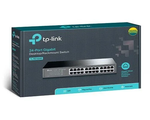
TP-Link
24-Port | Gigabit | Unmanaged
In Stock
TP-Link
24-Port | Gigabit | Unmanaged
In Stock
TP-Link
24-Port | Fast Ethernet | Unmanaged
In Stock
D-Link
24-Port | Fast Ethernet | Unmanaged
In Stock